Jeep Parts Wiki | GM Parts Wiki
Home | Search | Browse
|
Master Parts and Accessories Catalog FPS 8096-A October 1986 |
|
Prev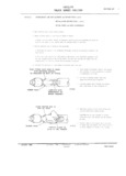
 Next
Next
9C705
9C705
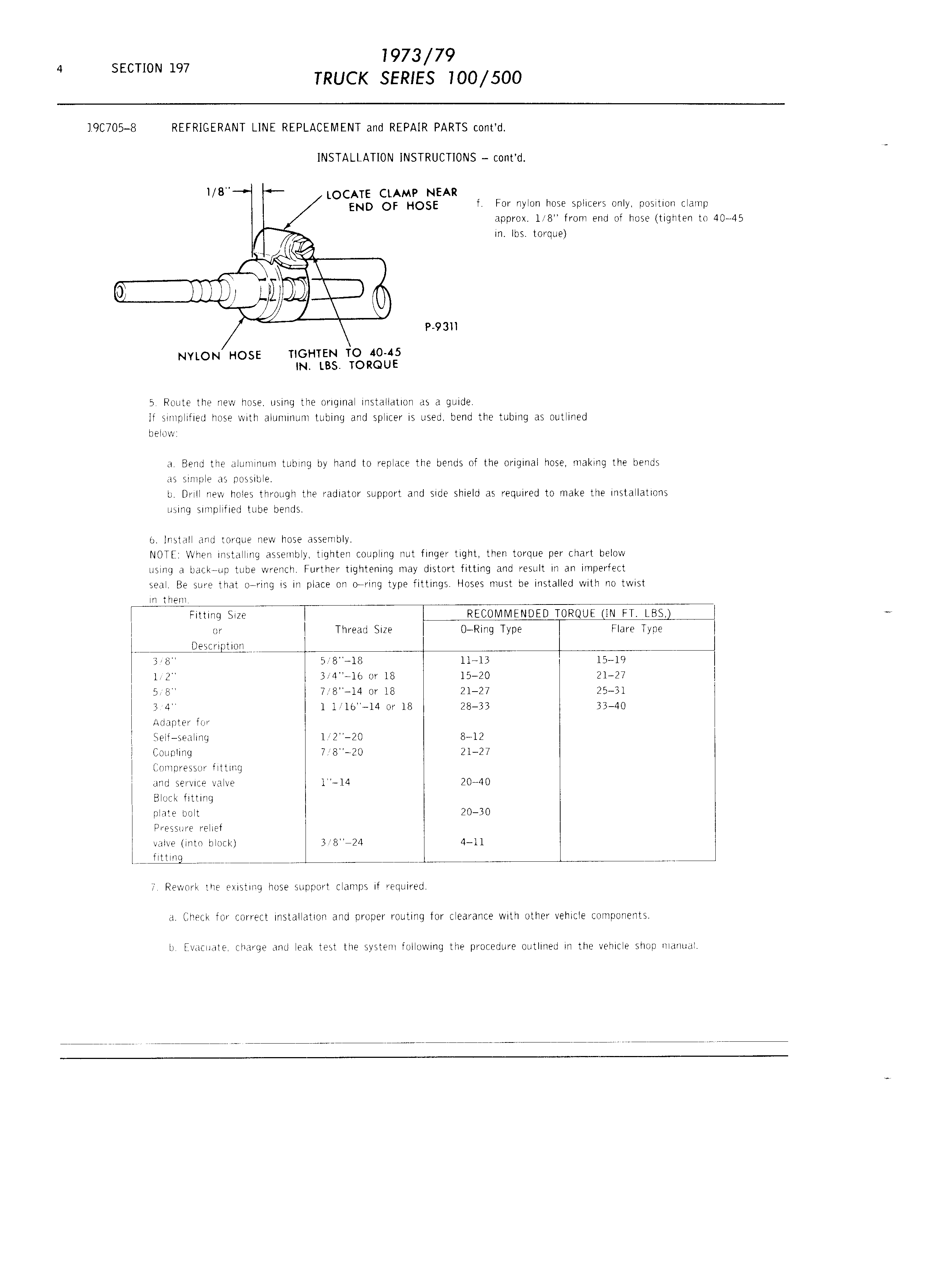
SECTION 197 muck SERIES 100 500 I9C705 8 REFRIGERANT LINE REPLACEMENT and REPAIR PARTS c0nt d INSTALLATION INSTRUCTIONS c0nt d l B LOCATE CLAMP NEAR END OF HOSE f For nylon hose splicers only posltion clamp approx 1 8 from end of hose tighten to 40 45 in lbs torque n l P 93ll NYLON HOSE TIGHTEN TO 40 45 IN LBS TORQUE 5 Route the new hose using the original installation as a guide If simplified hose with aluminum tubing and splicer is used bend the tubing as outlined below a Bend the aluminum tubing by hand to replace the bends of the original hose making the bends as simple as possible b Drill new holes through the radiator support and side shield as required to make the installations using simpllfied tube bends o Install and torque new hose assembly NOTE When installing assembly tighten coupling nut finger tight then torque per chart below using a back up tube wrench Further tightening may distort fitting and result in an imperfect seal Be sure that o ring is in place on twring type fittings Hoses must be installed with no twist lU them Fitting Size RECOMMENDED TORQUE IN ET LBS l or l Thread Size 0 Ring Type Flare Type l s l2 9 m li LL 3l8 5 8 18 11 13 15 19 I i 1 2 3 4 1o or 18 15 20 21 27 l l 5 8 7 8 I4 or 18 21 27 25 31 l l 3 4 1 Il Ib I4 or 18 28 33 33 40 l Adapter for l Self sealing 1l2 20 8 12 l Coupling 7 8 20 21 27 l Compressor flttmg l and service valve 1 14 20 40 l Block fitting l plate bolt 20 30 l Pressure relief l valve lnto block 3 8 24 4 I1 l s L sss s LLss1 MLLEE L Lss l 7 Rework the existing hose support clamps if required a Check for correct installation and proper routing for clearance with other vehlcle components b Evacuate charge and leak test the system following the procedure outlined in the vehicle shop manual